

Dell Changed the SATA Power Cable Pinout on the Dell Pro Tower / Pro Tower Plus range — Here's What's Different
If you're trying to add a second hard drive to a newer Dell desktop — like the Dell Tower ECT1250 or the wider Dell Pro Tower / Pro Tower Plus range (QCT1250, QBT1250, QVT1260, and similar) — and you've reached for an old Dell SATA power cable from a previous machine or the standard dell sata power cable listing on amazon and ebay you may have found it simply doesn't work, or worse, made you nervous enough to stop before plugging it in. You were right to be cautious.
Here's the short version: a Dell SATA power cable has a standard 15-pin SATA power connector on one end — the same connector every SATA hard drive and SSD uses — and a small proprietary 6-pin connector on the other end, which plugs into a header on the Dell motherboard labelled SATA_PWR. That header supplies 3.3V, 5V, 12V, and ground down to the drive through the cable.
The problem is that Dell hasn't kept the pin arrangement on that 6-pin SATA_PWR header consistent across generations. The physical connector looks the same — same shape, same 6-pin mini housing, noticeably smaller than a standard 6-pin PCIe power connector — but the position of the ground and voltage pins has moved between the older desktop generation (Inspiron-era machines like the 3650/3653/3655/3660/3668/3670) and the current Pro Tower / ECT1250-era generation. Plug an old cable in assuming the old pin order, and you can end up feeding voltage into what is now a ground pin, or vice versa — which is exactly the kind of mistake that damages a drive.
In this post I'll walk through what the SATA_PWR connector actually is, show the standard SATA power pinout for reference, and then lay out exactly how the pin arrangement differs between the old and new Dell connector, based on cable diagrams I decoded and tested directly on both an old and a new Dell tower.
What is the Dell SATA_PWR connector?
[PHOTO: motherboard header, labelled close-up showing "SATA_PWR" silkscreen text if visible]
On Dell's own motherboards, this connector is labelled SATA_PWR — it's a small, proprietary 6-pin socket that exists purely to power internal SATA drives (hard disks, SSDs, optical drives) that aren't included by default in a given configuration. It's separate from the main system power connector (the one that replaces a standard ATX 24-pin) — don't confuse the two, they're different connectors with different pinouts and different jobs.
Dell doesn't publish a public pinout for this connector, and — based on discussion in Dell's own community forums — Dell hasn't kept it consistent between models either. Cables designed for one generation aren't guaranteed to be safe on another, even when the physical connector looks identical.
How to read the pin diagrams in this post
Every diagram and photo below shows the male, fixed side of each connector — meaning the power port built into the SATA drive itself, and the SATA_PWR header built into the motherboard. Not the loose ends of the cable, which are the female sockets that plug onto those two fixed points.
To match the diagrams: pick up (or look at) the end you'd normally plug a cable into — the drive's power port, or the motherboard header — turn it so it's facing you, and look straight down into the pins. That's the viewing angle used throughout.
Pin 1, in both cases, sits on the side nearest the connector's keying feature:
On the standard 15-pin SATA power connector, pin 1 is the pin next to the raised notch that keys the connector so it can only go in one way round.
On the Dell 6-pin SATA_PWR connector — laid out as a 2×3 block of pins — pin 1 is the right-hand pin of the row nearest the keying arm/notch, using the same face-on viewing angle described above.
Keep that orientation consistent across every photo you add, or the pin numbers won't line up between shots.
The standard SATA power connector (for reference)
The end of the cable that plugs into the drive is a standard, industry-wide 15-pin SATA power connector—this part hasn't changed and isn't Dell-specific. It's useful as a reference point when you're tracing which Dell pin maps to which voltage. The 15 pins are actually 3 pins of the same usage, so pins 1 to 3 are labelled A, pins 4 to 6 are labelled B, and then we can just map A to E to the correct place on the Dell proprietary connector in the next section.
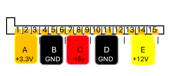
SATA_PWR Pinout Simplfied
SATA power — reference
15-Pin Connector Pinout
Standard SATA power connector, pin 1 through pin 15, with the usual PSU cable wire colour for each rail.
| Pin | Signal | PSU wire colour | Area Lebel | |
|---|---|---|---|---|
| 1 | +3.3VDC | orange | A | |
| 2 | +3.3VDC | orange | ||
| 3 | +3.3VDC | orange | ||
| 4 | GND | black | B | |
| 5 | GND | black | ||
| 6 | GND | black | ||
| 7 | +5VDC | red | C | |
| 8 | +5VDC | red | ||
| 9 | +5VDC | red | ||
| 10 | GND | black | D | |
| 11 | Optional | black | ||
| 12 | GND | black | ||
| 13 | +12VDC | yellow | E | |
| 14 | +12VDC | yellow | ||
| 15 | +12VDC | yellow |
Pin 1 sits at the end nearest the connector's keyed notch — the feature that stops it being inserted the wrong way round.
The Dell 6-pin SATA power pinout explains SATA_PWR
Those 5 different label area from A to E from the SATA Power connector now have to be mapped exactly to the SATA_PWR connector 6 pin connector on the dell mothboard. The 1st things to note is that the connector has 6 pins, but there are only 5 wires coming from the SATA power connector, so one will be unused. Also you will note there is 2 for GND, known as Ground.
This is the dell 6 pin mini connector pin out you 1st need to be clear which is pin1, the bottom right if you look into the connector with the notch at the bottom. Then from right to left on that bottom row 1,2 and 3, then back to the right on the top row from the right for 4,5 and 6.
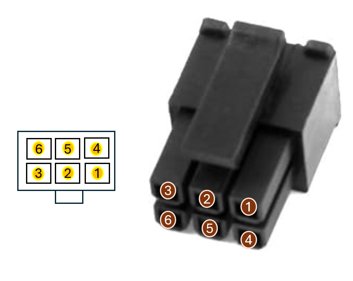
Dell SATA_PWR 6 pin connector pin layout simplfied.
The new Dell 6-pin SATA_PWR pinout (ECT1250 / Pro Tower range)
This maps the 5 outputs labelled A to E from your SATA power connector to the 5 used of the 6 connections available in the Dell SATA power connector, following this mapping table. It can be read as: Pin 1 from this connector goes to D on the SATA power connector, and so on: 2 to E, 3 to B, 4 to A and 5 to C, with 6 unused.
This newer connector has offical dell part numers 05GPWK (also written 5GPWK) and 0YJW72 (also written YJW72)
Newer Dell SATA power — reference
6-Pin Connector Pinout
Proprietary Dell SATA power connector, pin 1 through pin 6, with the usual PSU cable wire colour for each rail.
| Pin | Signal | PSU wire colour | Connect to SATA PWR Area | |
|---|---|---|---|---|
| 1 | GND | black | D | |
| 2 | +3.3VDC | orange | E | |
| 3 | GND | black | B | |
| 4 | +12VDC | yellow | A | |
| 5 | +5VDC | red | C | |
| 6 | NOT USED | NOT USED | - |
Pin 1 sits at the end bottom right with the notch down see the picture for clarity
Dell SATA_PWR — reference
Models Using the New-Style SATA Power Cable
Machines confirmed, at 80%+ confidence, to use the current-generation Dell 6-pin SATA_PWR pinout — the same cable sold under two Dell part numbers.
| Model | Range | Basis for confidence |
|---|---|---|
| Tower ECT1250 | Dell Pro Tower | Very highReference model — this cable and part number were confirmed directly in Dell's own community forum for this exact machine. |
| Pro Tower QCT1250 | Dell Pro Tower | HighSame part numbers cited consistently across multiple independent sellers, and discussed alongside the ECT1250 in Dell Community threads. |
| Pro Tower Plus QBT1250 | Dell Pro Tower Plus | HighSubject of its own dedicated Dell Community threads on adding a SATA drive using this cable. |
| Pro Tower QCT1255 | Dell Pro Tower | GoodSame part numbers cited across multiple independent seller listings alongside QCT1250 — not independently confirmed in a Dell Community thread of its own. |
| Pro Essential QVT1260 | Dell Pro Essential | GoodNamed specifically (not just bundled) in matching part-number listings across three separate marketplaces. |
Left out on purpose: Dell Pro Slim QCS1250 / Pro Slim Plus QBS1250 / Pro Max Slim FCS1250 use a different Dell part number (MX6YG) for the Slim chassis, not 05GPWK/0YJW72. OptiPlex 7020 SFF was reported by one Dell Community user to share the same pinout, but under its own separate part number (0PX7DC), not this one. Tower ECS1250 appeared in a single reseller listing only, with nothing corroborating it elsewhere — below the bar for this table.
The old Dell 6-pin SATA_PWR pinout
This maps the 5 outputs labelled A to E from your SATA power connector to the 5 used of the 6 connections available in the Dell SATA power connector, following this mapping table. It can be read as: Pin 1 from this connector is not used; then pin 2 goes to E on the SATA power connector, and so on: 3 to D, 4 to B, 5 to C and 6 to A.
The older connector has official Dell part numbers GP2JM as the primary number, and 5TK4F as a possible alternate reported specifically for the Inspiron 3670
Legacy Dell SATA power — reference
6-Pin Connector Pinout
Proprietary Dell SATA power connector, pin 1 through pin 6, with the usual PSU cable wire colour for each rail.
| Pin | Signal | PSU wire colour | Connect to SATA PWR Area | |
|---|---|---|---|---|
| 1 | NOT USED | NOT USED | - | |
| 2 | +3.3VDC | orange | E | |
| 3 | GND | black | D | |
| 4 | GND | black | B | |
| 5 | +5VDC | red | C | |
| 6 | +12VDC | yellow | A |
Pin 1 sits at the end bottom right with the notch down see the picture for clarity
Dell SATA_PWR — reference
Models Using the Older-Style SATA Power Cable
Machines confirmed, at 80%+ confidence, to use the older-generation Dell 6-pin SATA_PWR pinout — the connector this whole comparison started from.
| Model | Range | Basis for confidence |
|---|---|---|
| Inspiron 3650 | Inspiron desktop | HighPart number GP2JM cited identically across many independent sellers (Amazon, Newegg, direct manufacturer store), consistently naming this model. |
| Inspiron 3653 | Inspiron desktop | HighSame GP2JM listings as above — appears in nearly every one alongside 3650. |
| Inspiron 3655 | Inspiron desktop | HighConsistently named in the broader GP2JM listings covering the full Inspiron 36xx/32xx range. |
| Inspiron 3250 | Inspiron desktop | HighConsistently named in the broader GP2JM listings covering the full Inspiron 36xx/32xx range. |
| Inspiron 3252 | Inspiron desktop | HighConsistently named in the broader GP2JM listings covering the full Inspiron 36xx/32xx range. |
| Inspiron 3268 | Inspiron desktop | HighConsistently named in the broader GP2JM listings covering the full Inspiron 36xx/32xx range. |
| Inspiron 3660 | Inspiron desktop | HighConsistently named in the broader GP2JM listings covering the full Inspiron 36xx/32xx range. |
| Inspiron 3667 | Inspiron desktop | HighConsistently named in the broader GP2JM listings covering the full Inspiron 36xx/32xx range. |
| Inspiron 3668 | Inspiron desktop | HighConsistently named in the broader GP2JM listings covering the full Inspiron 36xx/32xx range. |
| Inspiron 3670 | Inspiron desktop | HighConsistently named in the broader GP2JM listings — though see the footnote on an alternate part number reported for this model specifically. |
| Inspiron V3668 | Inspiron desktop | HighConsistently named in the broader GP2JM listings covering the full Inspiron 36xx/32xx range. |
Left out on purpose: Inspiron 3253 and 3255 appeared in only one seller listing (everywhere else says 3252/3268), which reads more like a possible typo than a confirmed separate model — below the bar here. Vostro (3070/3670/3967/3977/3980) is explicitly excluded, since one seller's listing states its cable is "not for... Vostro" — meaning Vostro likely uses a separate pinout of its own that I haven't confirmed a part number for. OptiPlex is excluded for the same reason, and separately, is already known to be fragmented across several different Dell connector variants. One open question: a separate listing gives the Inspiron 3670 a different Dell part number, 5TK4F/05TK4F, apparently for a 2.5" HDD configuration — if GP2JM doesn't match what you find on a 3670 specifically, that's the number to check next.